
Closed and Ground vs Closed Un-ground Die Springs: Which End Type to Specify?
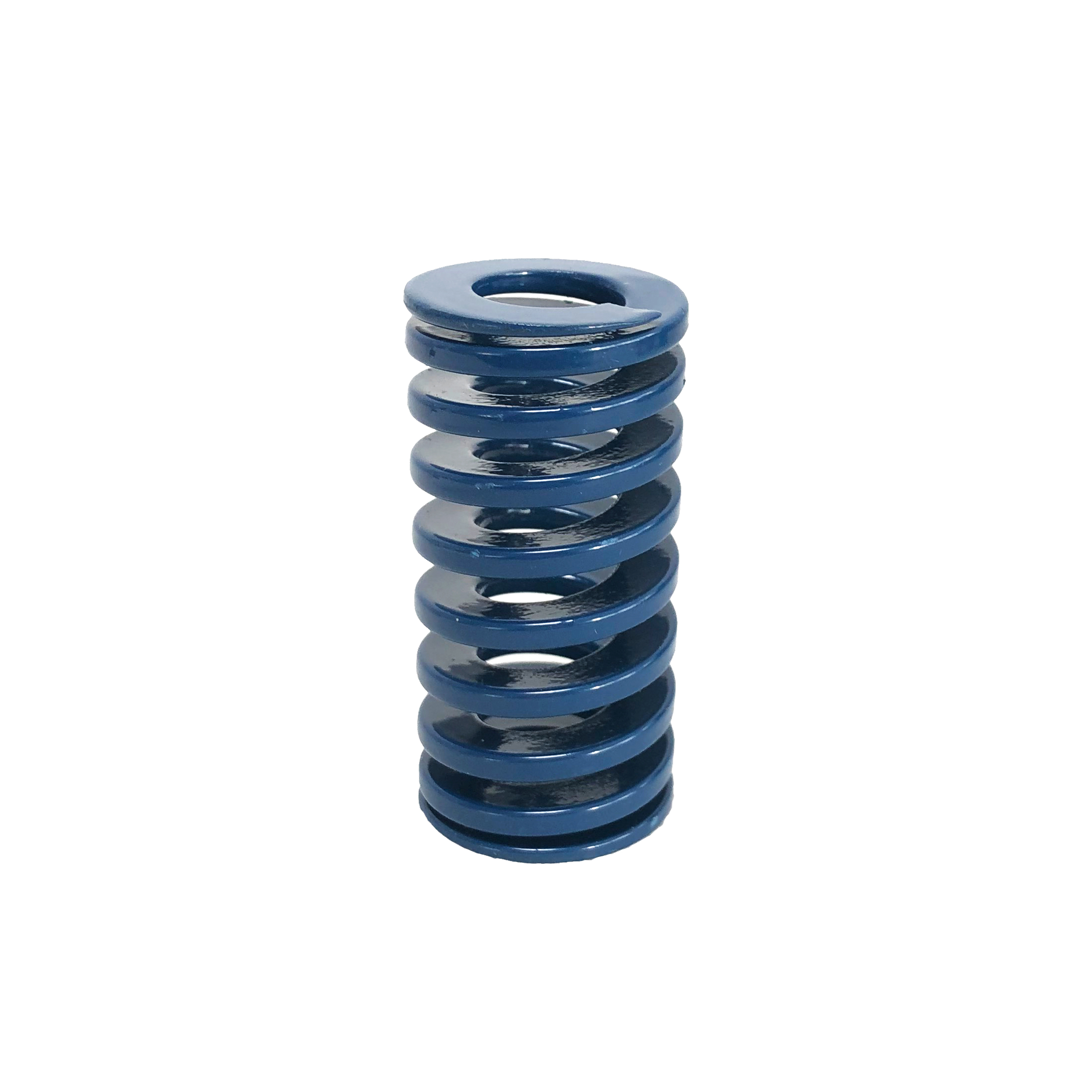
Closed and ground die springs have both end faces ground so they sit square to the spring axis, giving the pocket a flat, perpendicular surface to carry load. Closed un-ground die springs keep closed end coils but are not ground, and they remain an available option inside the same ISO 10243, JIS B5012 and American Standard series. The right choice is a statement about die set alignment and load path, not a matter of habit.
This guide compares the two end types the way a tool designer or maintenance buyer actually meets them: at the drawing stage, when the spring pocket is being defined and the die set is already fixed. It sets out what each end face does under load, how to match the end type to guide-post alignment and load class, and where a closed un-ground spring still fits without creating a weak point in the tool.
The Problem: An End-Face Detail That Decides How the Load Travels
A die spring does one job inside a press tool: it stores and returns energy along a defined axis. The spring pocket, the guide pin and the spring have to agree on that axis. When they do not, the spring is no longer being compressed purely axially, and the tool starts to compensate in places that were never designed for it.
The end face is where that agreement is either made or left to the surrounding hardware. A ground end face presents a flat, perpendicular bearing surface to the pocket. A closed but un-ground end face presents closed coils, but the face itself has not been prepared to that condition. Both are legitimate products; they simply place the responsibility for squareness in different places.
The symptoms of getting this wrong are rarely dramatic at first. They show up as uneven wear on guide components, as springs that do not return to a clean seated position, and as load behaviour that no longer matches the load-deflection curve the tool was designed around. By the time those symptoms are visible, the conversation has usually moved from springs to rework.
Decision rule of thumb: if the die set relies on tightly guided alignment and the pocket is machined as a perpendicular seat, specify closed and ground. If the pocket seat itself controls the spring's position and the tool tolerates a non-ground face, closed un-ground stays on the table.
Industry Background: Why Rectangular Die Springs Carry Two End Options
Rectangular wire die springs are the default elastic element in press tools because of energy density. Per TopWay product documentation, the rectangular cross-section stores up to 30% to 50% more energy than round wire springs of the same footprint, which is why a die spring pocket can stay compact while still delivering the force a stamping or ejection sequence needs.
That density sits inside a standardised envelope. ISO 10243:2019 standardises colour-coding and dimensions for rectangular-section compression springs used in press tools, and JIS B5012 specifies allowable tolerances on the inner and outer diameters of springs, with a different focus from ISO 10243's mounting-hole orientation. Because the load class, colour and envelope are pinned by these systems, buyers can compare springs across suppliers — but the standards-driven envelope is also why the end type is often carried along as a catalogue option rather than re-examined for each tool.
Demand keeps pushing that envelope harder. Grand View Research projects the global industrial springs market to reach USD 7.1 billion by 2033, and the automotive stamping market alone was valued at USD 87.98 billion in 2024 according to Market Research Future — a large end-use base for die springs used in automotive stamping dies, plastic injection molds and die casting tooling. More cycles, tighter clearances and higher load classes all make the seating condition of the spring end face matter more, not less.
TopWay springs are manufactured in 55CrSi chrome silicon steel, shot-peened and multi-stage tempered, and are rated for a fatigue life of 3 to 5 million high-frequency compression cycles within a 12%–40% compression stroke (TOPWAY SPRINGS published data). That service window only holds if the spring is loaded the way the curve assumes — axially, with a preload, in a pocket that is square to the axis.
What Each End Type Actually Does Under Load
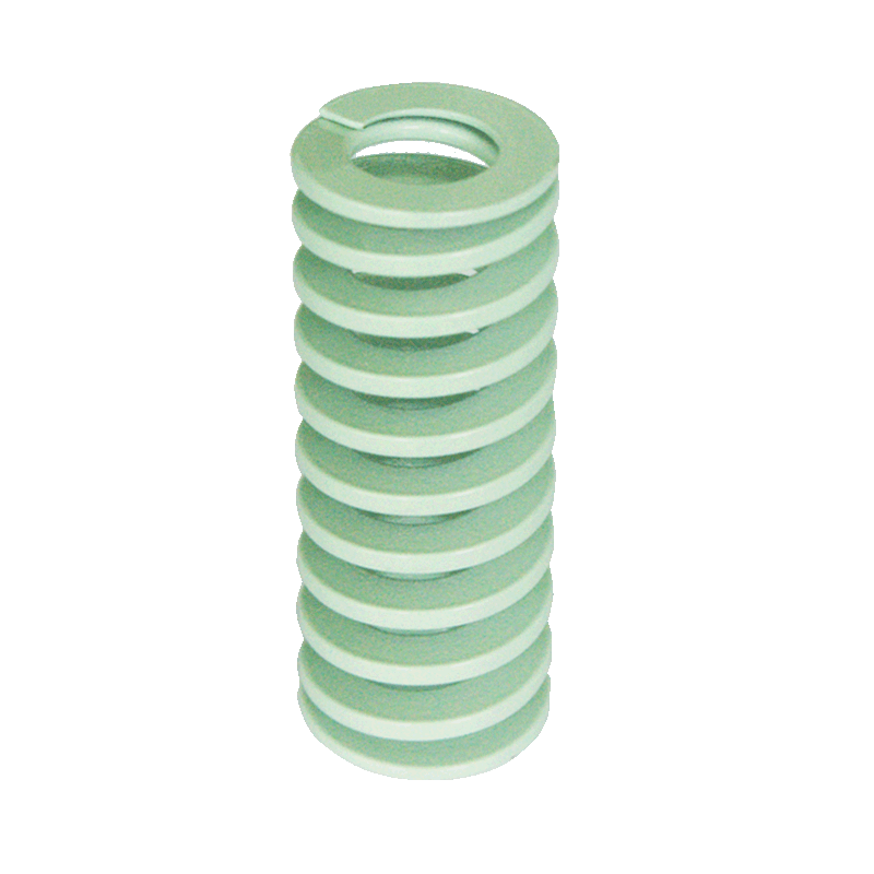
Closed and ground: a prepared bearing face
In a closed and ground spring, the end coils are closed and the end faces are then ground. The functional result, as described in TopWay product data, is precision ground parallelism: the ground end faces ensure squareness and perpendicular load distribution. That combination is what removes lateral deflection from the load path and protects the mold guide components from side loading they were not sized for.
Practically, this means the spring arrives able to define its own seating plane. The pocket still has to be machined correctly, but the spring no longer depends on the pocket edges or on installation clearance to keep the load travelling along the axis. In guided die sets, where the guide post and bushing set an alignment the tool cannot deviate from, that is the condition the design assumes.
Closed un-ground: a closed coil without a prepared face
In a closed un-ground spring, the end coils are closed but the end faces are not ground. It remains an available option within the same TopWay series — the ISO 10243, JIS B5012 and American Standard catalog ranges are all specified with End Type: Closed and Ground / Closed Un-ground. Nothing about the material, the 55CrSi grade, the powder coating or the load class changes.
What changes is where squareness comes from. Because the end face is not ground, squareness and perpendicular load distribution are not established by the spring end itself; they have to be established by how the spring seats in the pocket. That is acceptable where the seat geometry is controlled and the tool does not depend on the spring's end face to hold alignment — and it is a genuine risk where it does.
Load class is chosen first, end type second
End type never overrides load class. In the ISO 10243 range the classes run CIF super minimal load (light green), CIL light duty load (green), CIM medium duty load (blue), CIH heavy duty load (red) and CIB extra heavy duty load (yellow), across outer diameters of 10–63 mm, inner diameters of 5–38 mm and free lengths of 25–305 mm. The JIS B5012 range runs CSWF minimal load (yellow), CSWL light load (blue), CSWM medium load (red), CSWH heavy load (green), CSWB extra heavy load (brown) and CSWG super heavy load (black), across outer diameters of 6–70 mm, inner diameters of 3–38.5 mm and free lengths of 10–350 mm. The American Standard range covers medium duty (blue), medium heavy duty (red), heavy duty (gold) and extra heavy duty (green) springs, with outer diameters of 10–51 mm, inner diameters of 4.76–25.4 mm and free lengths of 25–305 mm.
Select the load class and the deflection first, then decide the end type within that class. Reversing the order is how tools end up with a correctly ground spring that is in the wrong load band.
Step-by-Step: Matching End Type to Die Set Alignment and Load
Step 1 — Define the seat, not just the pocket diameter. Establish whether the pocket presents a perpendicular, machined seat to the spring end face. If it does, a ground face can do its job. If the spring is located by surrounding geometry instead, record that explicitly, because it is the assumption the end type will rest on.
Step 2 — Read the die set's alignment dependency. In a die set built around guide posts and bushings, the spring must not add lateral load to an already constrained assembly. That points to closed and ground. Where the tool's guidance is generous and the spring pocket alone controls position, closed un-ground can be evaluated on its own merits rather than excluded by default.
Step 3 — Fix the load class and colour code first. Match the required force and deflection to the correct ISO 10243, JIS B5012 or American Standard class. Note that colour conventions differ between systems — JIS minimal load is yellow while ISO super minimal load is light green — so confirm the class by model code, not by colour alone.
Step 4 — Check deflection against the service window. TopWay springs are rated for 3 to 5 million high-frequency compression cycles within a 12%–40% compression stroke, and long-life operation is generally planned around deflections in the region of 30%–35% of free length. If the tool runs near the top of the stroke range, the seating condition becomes more critical, which favours a ground end face.
Step 5 — Specify preload. Installation should apply an initial preload, typically 5%–10% of free length. Preload removes internal play and prevents the shock loading that causes spring chatter, lateral buckling and early structural failure. Preload and end type work together: preload keeps the spring seated, and a ground face keeps the seated spring square.
Step 6 — Verify documentation and interchangeability. Confirm that the part is supplied against ISO 10243, JIS B5012 or American Standard dimensions as required, that material is 55CrSi with a mill test certificate and heat-number traceability, and that the end type is stated on the order line and the packing, not only in the drawing notes.
Use Cases: Where the Decision Changes
Automotive stamping dies
High-cycle automotive stamping runs combine tight guide clearances with continuous preloaded operation. This is the classic closed and ground application: the spring must return the stripper or pressure pad without introducing sideways force into guide posts and bushings, and the tool is expected to run for millions of strokes.
Injection molds and die casting tooling
Ejection systems rely on even force distribution across the ejector plate. Where the plate and pocket are machined square and the assembly is guided, closed and ground ends keep the load path perpendicular. In die casting tooling, the same requirement meets higher ambient temperatures, which is where multi-stage tempering and resistance to thermal relaxation become part of the end-type decision rather than a separate topic.
Automation, machine tools and general machinery
TopWay Series springs are also used in industrial automation, elevator systems, machine tools, engineering machinery, environmental filtration equipment, high-voltage electrical switches, valves and heavy-duty energy systems. In these assemblies the spring pocket is often part of a fabricated housing rather than a precision die plate, and the seating condition — not the catalogue default — should decide the end type.
Maintenance and MRO replacement
When a spring is replaced during a press stoppage, the safest approach is to match the original specification, including end type, unless the failure analysis points to a seating problem. Upgrading an un-ground position to a ground spring does not fix a pocket that is out of square; it only removes one possible contributor.
Comparison Table: Closed and Ground vs Closed Un-ground
| Decision factor | Closed and Ground | Closed Un-ground |
|---|---|---|
| End-face condition | End coils closed and end faces ground | End coils closed, end faces not ground |
| Squareness to the spring axis | Ground parallelism provides squareness | Squareness is not established by the end face |
| Load transfer | Perpendicular load distribution across the end face | Load transfer depends on the pocket seat |
| Lateral deflection | Ground faces eliminate lateral deflection | Not addressed by the end face itself |
| Effect on guide components | Protects mold guide components from side load | Relies on the die set's own guidance |
| Availability | Offered in ISO 10243, JIS B5012 and American Standard series | Offered in the same series and load classes |
| Material and process | 55CrSi, shot-peened, multi-stage tempered, powder coated | Identical material and process |
| Where it fits | Guided die sets, perpendicular machined seats, high-cycle tooling | Pockets where the seat, not the spring face, controls alignment |
Frequently Asked Questions
Do closed and ground and closed un-ground die springs follow the same international standards?
Yes. Both end types are supplied within TopWay's ISO 10243, JIS B5012 and American Standard (Inch series) product ranges, and the end type is listed as Closed and Ground / Closed Un-ground across the ISO 10243, JIS B5012 and American Standard specifications. ISO 10243:2019 standardises colour-coding and dimensions for rectangular-section compression springs used in press tools, while JIS B5012 specifies allowable tolerances on inner and outer diameters. TopWay manufactures springs that adhere to all three specifications, so the choice between end types does not change the dimensional system the spring belongs to.
Which end type supports die set alignment and protects guide components?
Closed and ground. The ground end faces provide precision ground parallelism, which ensures squareness and perpendicular load distribution, eliminates lateral deflection and protects mold guide components. That behaviour is supported by the rest of the construction: 55CrSi oil-tempered alloy steel, precision shot-peening and multi-stage tempering, rated for 3 to 5 million high-frequency compression cycles within a 12%–40% compression stroke. Installing with an initial preload of 5%–10% of free length keeps the spring seated against the pocket and completes the alignment chain.
Are both end types available from stock, and how should the choice be weighed commercially?
TopWay maintains extensive buffer stock across standard ISO, JIS and American catalog items, with both end types offered within those series, and supplies at factory-direct pricing as a direct manufacturing plant. The commercial question is better framed as risk than as a line-item difference: an end face that does not match the pocket's seating condition puts guide components, pockets and press time at risk, and that exposure should be weighed against the specification. Custom end configurations, non-standard dimensions and private branding are also available under OEM/ODM terms.
Can a spring with a specific end type be produced from drawings or a physical sample?
Yes. TopWay supports full OEM/ODM customization, including custom wire profiles, non-standard load specifications, non-standard outer and inner diameters, specialised surface treatments, colour-coded powder coatings and private-label branding based on customer drawings or physical samples. Every raw material batch is supplied with a mill test certificate and heat-number traceability, so a sample-built part can be documented back to its steel lot.
What are the lead times for standard and custom end-type orders?
Standard catalog springs held in the ready-to-ship inventory are typically dispatched within 24 to 48 hours. Custom engineered or bulk OEM orders are generally delivered within 2 to 3 weeks, supported by automated coiling and grinding lines and flexible production scheduling. To confirm an end type against your die set, send the pocket drawing or a photo of the seat together with the load class and free length — a sample request or quote can be started from that information alone.
Conclusion: Let the Pocket Decide the End Face
The comparison between closed and ground and closed un-ground die springs does not end in a universal winner. It ends in a rule: the end face should match the way the tool establishes alignment. Where the die set is guided and the pocket is machined as a perpendicular seat, a closed and ground spring carries the load the way the design assumes — square to the axis, without lateral deflection, and without transferring side load into guide components. Where the seat geometry itself controls the spring's position, closed un-ground remains a valid, available option within the same standards and load classes.
Both decisions become safer when the rest of the specification is disciplined: correct load class by model code rather than colour habit, a preload of 5%–10% of free length, deflection planned inside the 12%–40% stroke window, 55CrSi material with heat-number traceability, and documentation that states the end type on the order and the label.
Need Help Matching an End Type to Your Die Set?
TOPWAY SPRINGS is the spring division of Dalian TopWay Precise Mould & Die Co., Ltd., a precise mould and die parts manufacturer founded in 2012, operating a 16,500 m² facility in Dalian, Liaoning, China, with 58 employees, 5 R&D engineers and an annual output of 3,600,000 pieces. The company manufactures die springs to ISO 10243, JIS B5012 and American Standard (Inch series) specifications and exports to the EU and USA.
Send your pocket drawing, load class and free length to request a sample or a quotation: liya@chs-spring.com · Tel / WhatsApp +86 151-4047-4905 · www.onetopway.com
Download the full product catalogue: Dalian TopWay Product Catalogue (PDF)

Have Questions or Need More Details?
Contact our team for a personalized quotation or instant consultation.
Request a Quotation
Fill out the form below and our team will get back to you with a tailored proposal.
WhatsApp Direct Chat
Prefer to chat in real-time? Message us on WhatsApp for instant assistance & quick answers.
- Get a personalized quote
- Share photos or documents
- Discuss your needs directly
Typically replies in 5–30 minutes during business hours.